
|
|
|
|
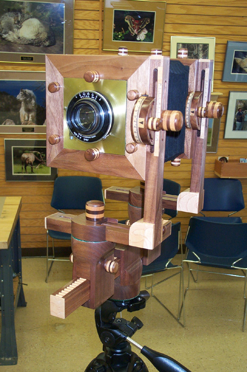
Front and Rear Standards (Complex)
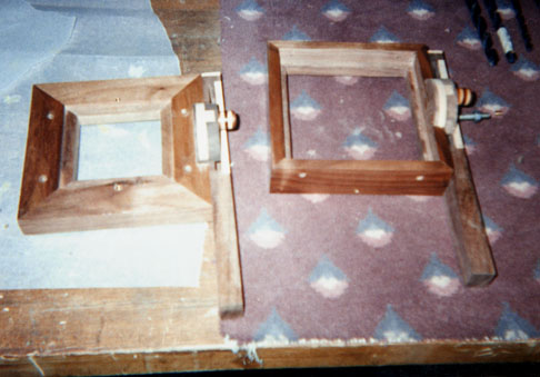
This is the vertical arm of the standards before adding the base arms and markings.
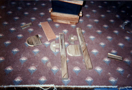
This is the exploded view of the vertical arm of the standards before adding to the camera body.
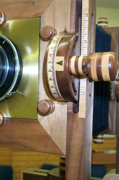
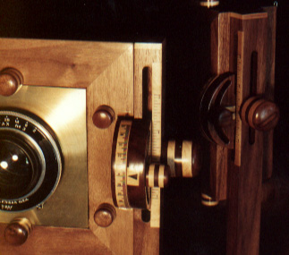
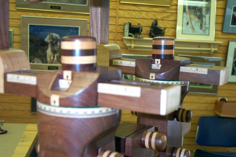
These are close-ups of the Rise/Fall/Tilt mechanism. You can see the channels routed into the vertical standard in detail in both views. This design will take a bit more work but I think it is a really elegant system. This is quite a complex process so please refer to the pictures and feel free to email me and ask questions. The camera is made of walnut, which is quite dark, so I added maple inserts at the critical locations so that the "engraved" markings would show up. If you use a lighter wood, of course, you wouldn't have a need for the inserts. Standard Construction Below is a drawing of the standard itself, without the pieces that allow you to rotate the frames. It's easy to machine these pieces. You will be cutting three pieces, the vertical and horizontal standards and the maple insert. The two standards should be easy cuts to dimension. While cutting them to size should be easy enough I'll go over how to cut the channels. I used a table router to cut the channels. I cut the through channels in six or seven passes using a 1/4" straight bit. This is the channel that you will use to tighten the camera body to the standard (the shorter of the two). Go slow and set really good start/stop points on the table fence. Take special care when you finally cut through. In fact, this should be the most shallow of your cuts so you don't get tear-out, or use a piece of scrap on the final cut. As always, measure for center then measure again. Now, the front channel should be really easy. It is a bit longer and, while not going through the standard, will cut through to your first channel. This is the channel that will limit the travel of, and hold secure, the rotation piece of your rise/fall/tilt mechanism. Cut the same as the first channel but ensure that you cut it deep enough to accept the rotation piece fully (about 13/16"). The insert gives the piece stability although you could change the dimensions so both the vertical and horizontal standards are the same width and then dovetail the two together. I think that would be a bit time consuming though since you would have to dovetail on a miter. The horizontal and vertical are attached in this plan on a miter with the 1 1/2" square insert cut to fit flush. I cut the insert with a 1" dado on a table saw. Start by cutting the dado lengthwise centered along a 1 1/2" wide length of wood that will be at least long enough for both inserts. Longer is safer in this case. Make at least two passes for safety since the final dado will be 3/4" deep. Next, cut the ends centered on the dado as well. Use a piece of backing scrap to eliminate tear-out and ensure you clamp the piece of wood well to get a clean cut. Again, two passes at least for safeties sake. Once these two cuts are done you should cut the the ends off to make 1 1/2" square inserts. Glue up is a bit of fun so please be patient. You have two choices, glue up the the mitered standards then put in the insert (you'll get glue everywhere!) or try to glue all three pieces at once (a little harder to ensure the standards are square. Either way you go this will take a bit of fun to complete. For my camera I added maple ends to the arms of the standards for aesthetic reasons. If you do add them ensure you take the width of the inlays into account for the overall dimensions. Once you are done here the standards are ready for sanding and finish.
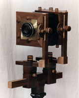
Swing Arm Construction Below are drawings of the pieces that allow the frames to rotate. Cut these pieces and inlay the anchor piece flush into the camera frames centered along the right side when looking at the front on the frame. The rotation piece will freely float inside of the vertical arm of the standard. The curve isn't exactly a half circle. If you drill the pivot point first (1/4" hole on the rotation piece) and attach a cord to the anchor and add a pencil to the other end you should be able to draw the line for both the outside curve and the channel for the tilt stop. I'm not a mathematical genius so the actual math involved is lost to me. I figure that as long as it works the math is irrelevant. If there are any math wizards out there that want to figure this out I'd be glad to post it here. Do NOT drill the hole for the pivot point in the anchor pieces. Wait till they are inlayed to the camera so you can drill them to size for the threaded insert. You can see in the pictures above what the finished product should look like and how the two pieces work together. I used a band saw to cut the pieces to size, a router to cut the indent on the back of the rotation piece and a scroll saw for the stop channel on the rotation piece.
This is the Shift/Swing part of the Standards. I'll go over how I made those in the Slider section. This completes your Standards! |